
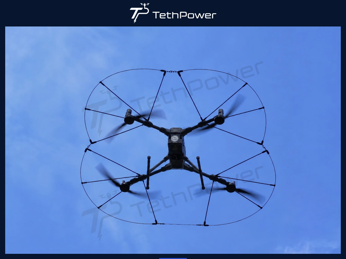
Application: physical propeller protection for close-proximity industrial inspection, indoor work and obstacle-rich missions
Quick Answer
A DJI Matrice 400 propeller guard adds a physical buffer around the propeller perimeter when the aircraft approaches walls, beams, vegetation or other obstacles. The single-rail and triple-rail architectures address different payload and coverage priorities. Neither makes the aircraft collision-proof, and both require configuration-specific installation and flight validation.
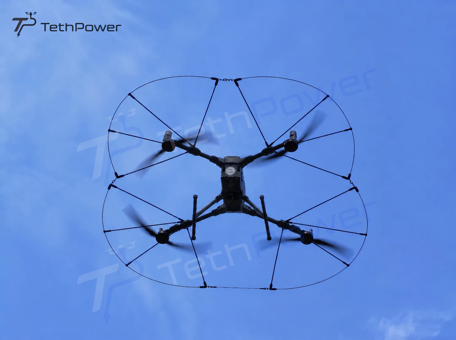
Figure. The guard is one layer in a broader flight-safety system.
Why a Physical Barrier Is Different from Obstacle Sensing
Industrial aircraft may operate beside façades, steel frames, branches, cables and confined structures. Obstacle sensing supports the pilot, but it is not a physical barrier around the propeller disk. A guard adds passive separation intended to reduce the chance that light contact becomes direct blade contact.
Treat the guard as a risk-reduction layer, not permission to fly closer or faster.
Combine mission planning, a trained pilot, obstacle sensing, conservative handling, physical guarding and controlled test flights.
Follow the aircraft limits, local operating rules and project risk controls for every mission.
Two Guard Architectures
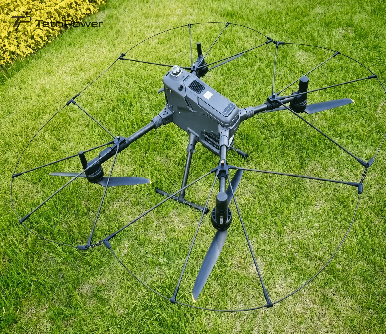
Figure. Single-rail architecture with one perimeter rail.
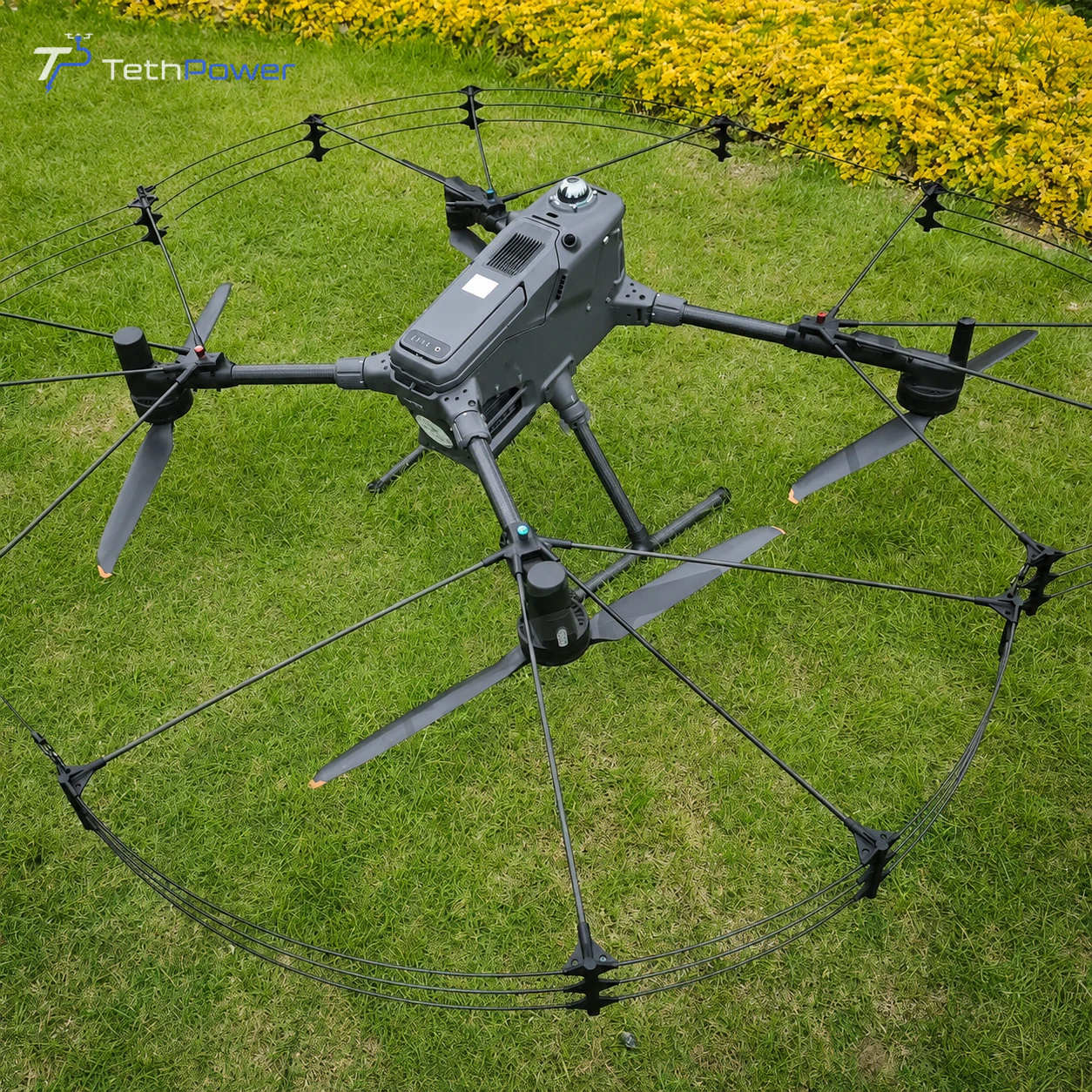
Figure. Triple-rail architecture with three perimeter rails.
Scroll horizontally to read the full table
Confirm the current guard revision, aircraft hardware, payloads and final installed configuration before ordering or flight testing.
Selection Framework
Scroll horizontally to read the full table
Available mission payload must account for the guard, every other installed accessory and the required safety margin. Do not estimate endurance from guard architecture alone; measure it with the final aircraft configuration.
Before quotation, confirm the simultaneous payloads, nearest expected obstacle, indoor or outdoor environment, planned navigation mode, validated handling envelope and applicable permits.
Mechanical Architecture and Integration
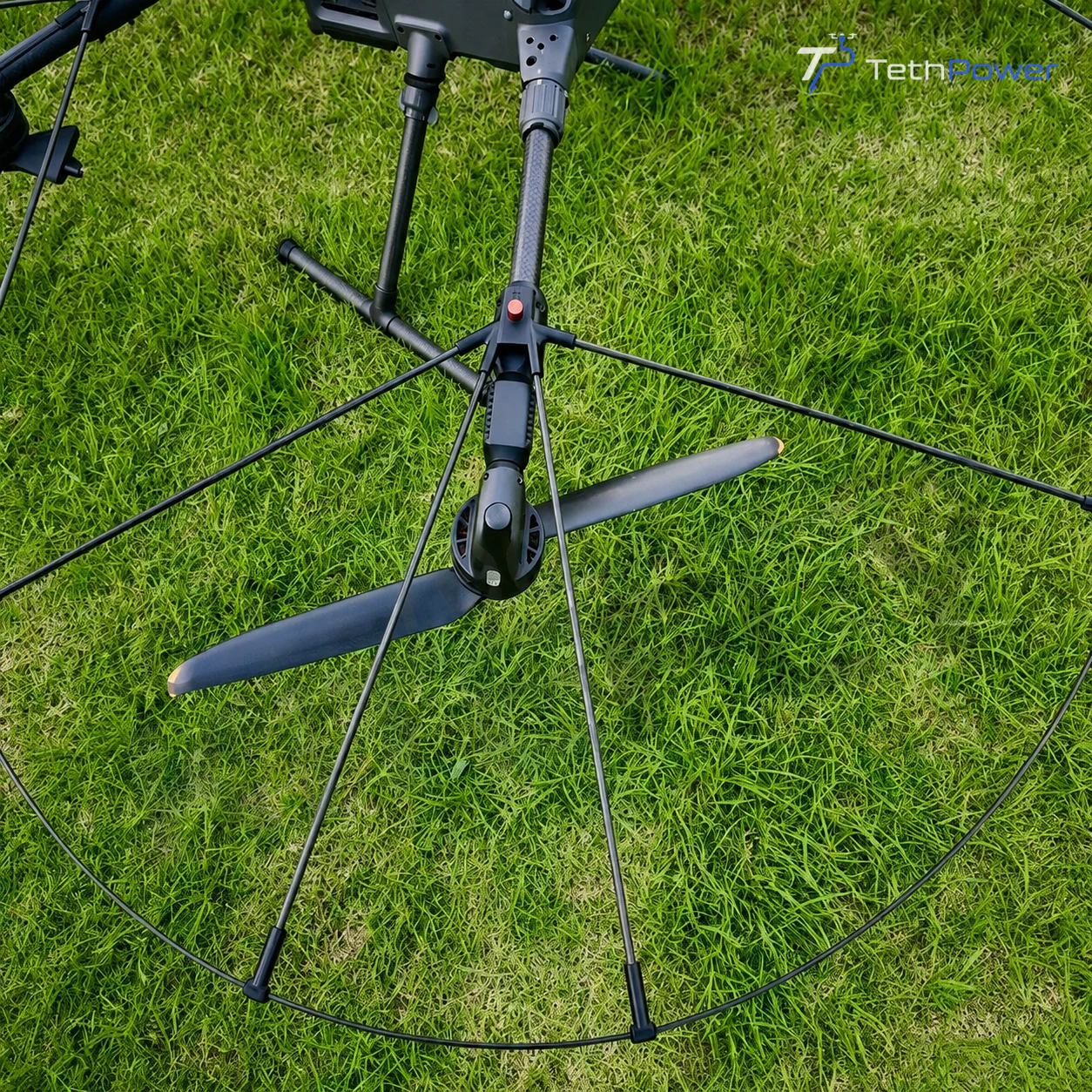
Figure. Single-rail arm interface and radial supports.
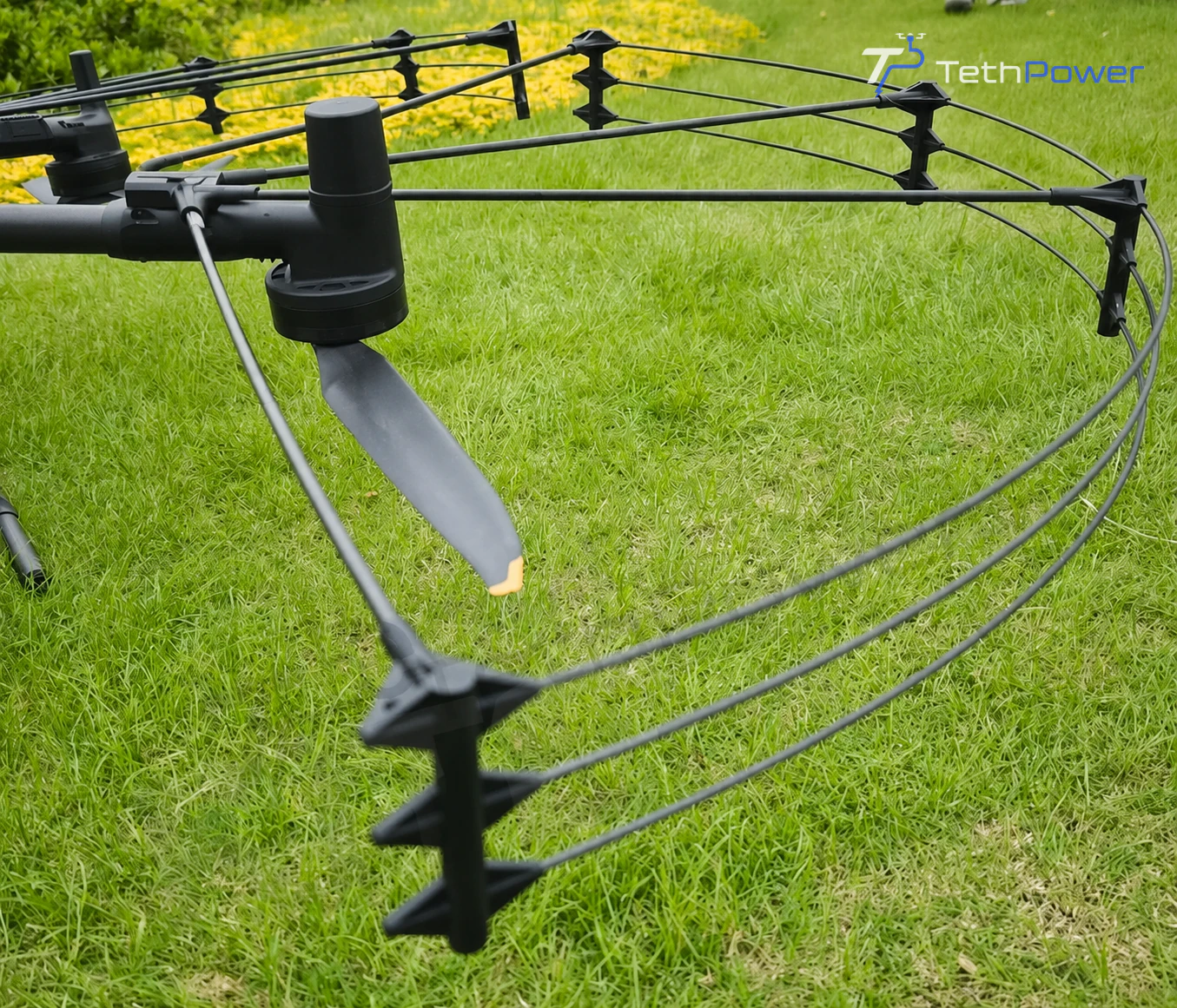
Figure. Triple-rail spacing, standoffs and perimeter structure.
Scroll horizontally to read the full table
Installation and Validation Workflow
Record the aircraft revision, payloads, batteries, firmware, guard revision and total installed mass.
Assemble the clamps, rails, links, fasteners, lanyards and tension wires on a clean, level surface.
Confirm the propeller plane remains parallel to the guard and that the structure cannot deflect into a blade.
Power the aircraft, review warnings and check that sensors, indicators, payloads and moving parts remain unobstructed.
Conduct a controlled low-hover test with a clear emergency landing area.
Expand the test envelope gradually while checking handling, braking, wind response, payload balance and mission geometry.
Pre-flight Checklist
All arm clamps are fully seated and locked.
The guard is level and clear of every propeller disk.
Perimeter rails, radial links, lanyards and tension wires are secure.
Sensors, indicators, payloads, cables and folding joints remain unobstructed.
Installed mass and center of gravity remain within the approved project configuration.
The test area is clear and the pilot has an immediate landing plan.
Operational Limits and Safety Boundaries
Scroll horizontally to read the full table
Frequently Asked Questions
Does a propeller guard make the DJI Matrice 400 collision-proof?
No. It adds a passive physical buffer around the propeller perimeter, but impact energy, angle, guard deformation, wind and aircraft control can still lead to propeller contact or loss of stability.
Which M400 propeller guard is better: single rail or triple rail?
Neither is universally better. The single-rail architecture prioritizes a simpler installation, while the triple-rail architecture provides a wider lateral barrier. Choose according to payload margin, obstacle geometry, flight environment and tested handling.
Will the guard block the M400 obstacle sensors?
The design intent is to keep sensing zones open. The installed aircraft still requires a powered sensor and warning check because accessories, assembly and hardware revisions can affect the final field of view.
Is the triple-rail version suitable for indoor inspection?
It can be a useful starting point where lateral contact risk is high, but indoor suitability also depends on navigation mode, lighting, airflow, control response, emergency landing space and local procedures.
How does the guard affect flight time?
No universal endurance reduction should be claimed without a controlled test. Added mass and drag can reduce endurance, while wind, payload, temperature, altitude, battery condition and flight profile also affect the result.
Do you supply the DJI Matrice 400 aircraft?
Aircraft availability, export eligibility and local procurement must be confirmed separately. We support guard selection, integration planning and technical configuration for the customer-procured or locally sourced aircraft.
Related Technical Resources
Request a Configuration Review
Send the aircraft revision, payload list, mission environment, nearest obstacle distance, intended handling envelope, expected wind conditions, local operating rules and delivery country. We will review the guard architecture and integration boundary for the M400 mission.
Compatibility and performance must be verified on current hardware. DJI and Matrice are trademarks of SZ DJI Technology Co., Ltd. References to DJI products describe intended compatibility and do not imply endorsement unless expressly stated.
| Contact | Stella |
|---|---|
| Website | www.tethpower.com |
| stella@ | |
| WhatsApp / Tel | +86 177 1431 2943 |