
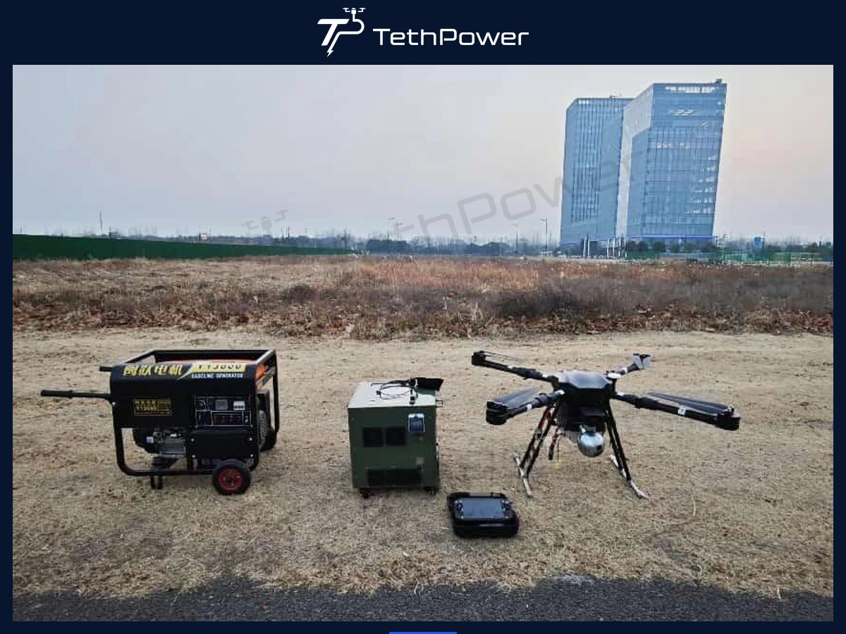
Historical project: This deployment illustrates a fiber-optic tethered surveillance configuration. Customer and location details are confidential. Contact us to discuss the equipment and integration requirements for your project.
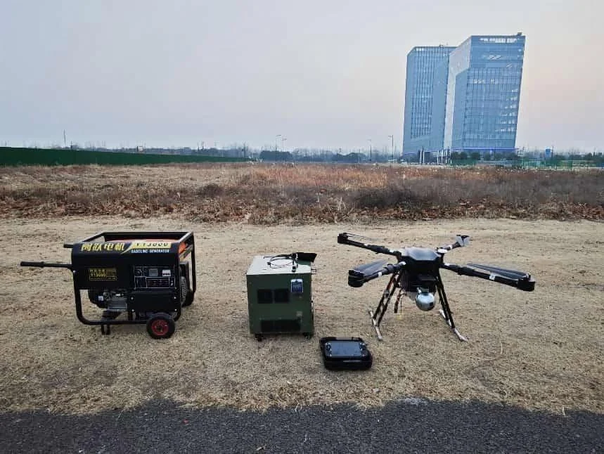
Reference field deployment with generator, tethered ground station and surveillance UAV.
The Mission Requirement
The customer needed a surveillance aircraft that could remain above a defined area for extended periods while carrying both visible-light and thermal imaging. Battery-only endurance was a poor fit because repeated landings interrupted observation. The project also required a control/video path that would not rely on the normal wireless link for the primary mission data.
Scroll horizontally to read the full table
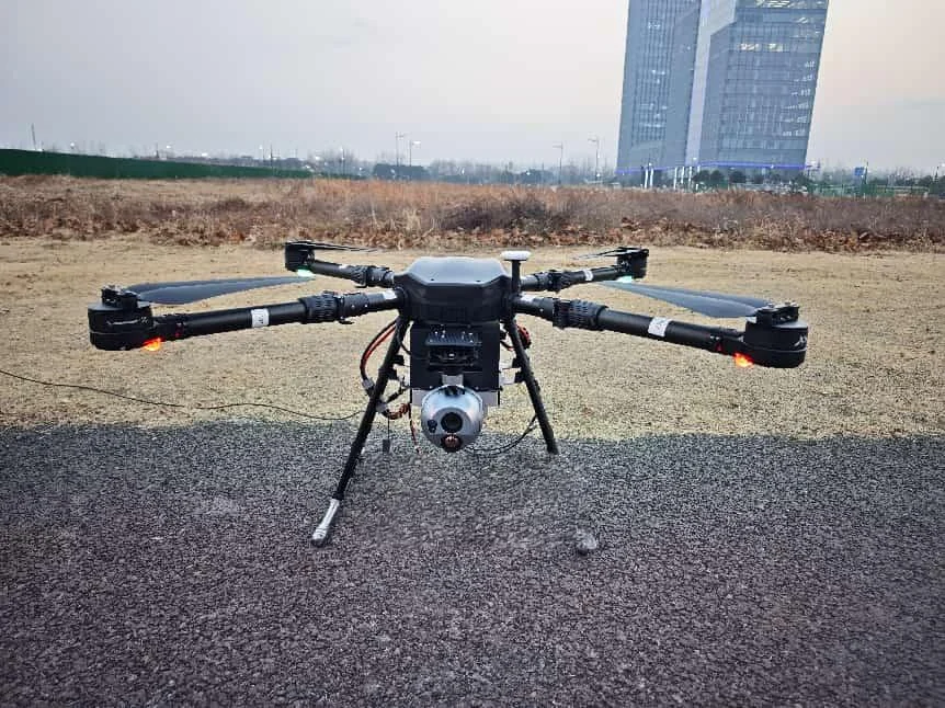
Reference surveillance UAV equipped with an EO/thermal payload.
Why Combine Power and Optical Fiber in the Tether?
Persistent surveillance has two separate continuity requirements: the aircraft needs energy and the command center needs a stable data path. The reference system combined high-voltage conductors and optical fiber in the tether so the main control/video path could be carried by cable while the aircraft received continuous ground power.
This reduces dependence on RF for the primary tethered control/video link. Other aircraft functions, such as GNSS or backup links, may still use radio-frequency systems and remain susceptible to interference.
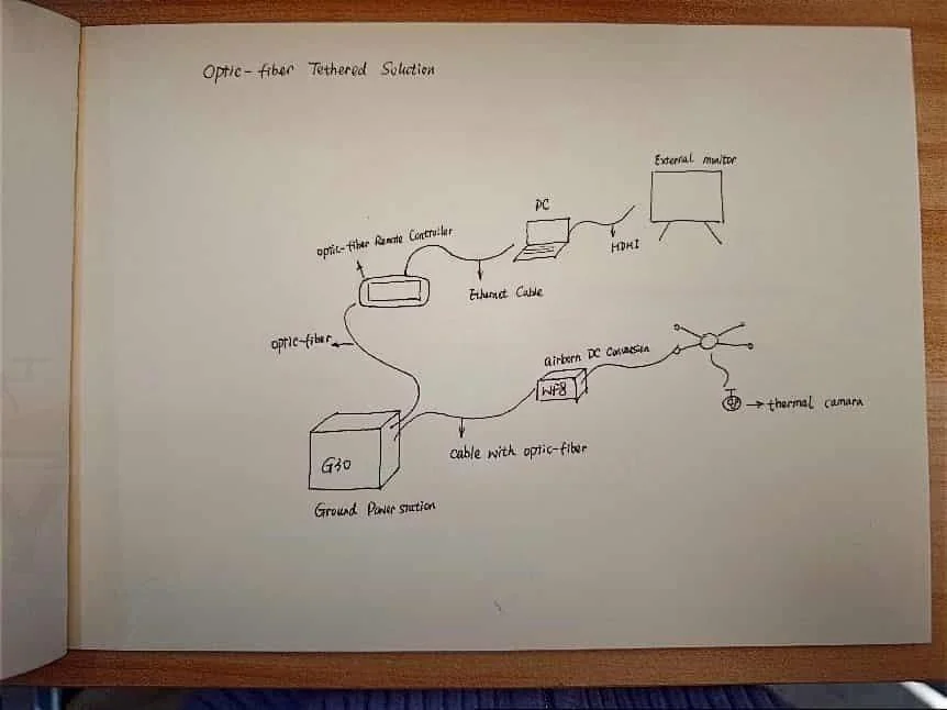
Reference architecture sketch showing ground power, optical-fiber controller, PC/HDMI display and airborne conversion.
Reference Delivered Configuration
G30 Tethered Ground Power Station
Scroll horizontally to read the full table
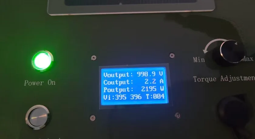
Ground-system display during reference operation, showing high-voltage tether output.
WF8 Regulated Airborne Power Module
Scroll horizontally to read the full table
UAV, Payload and Fiber Control
Scroll horizontally to read the full table
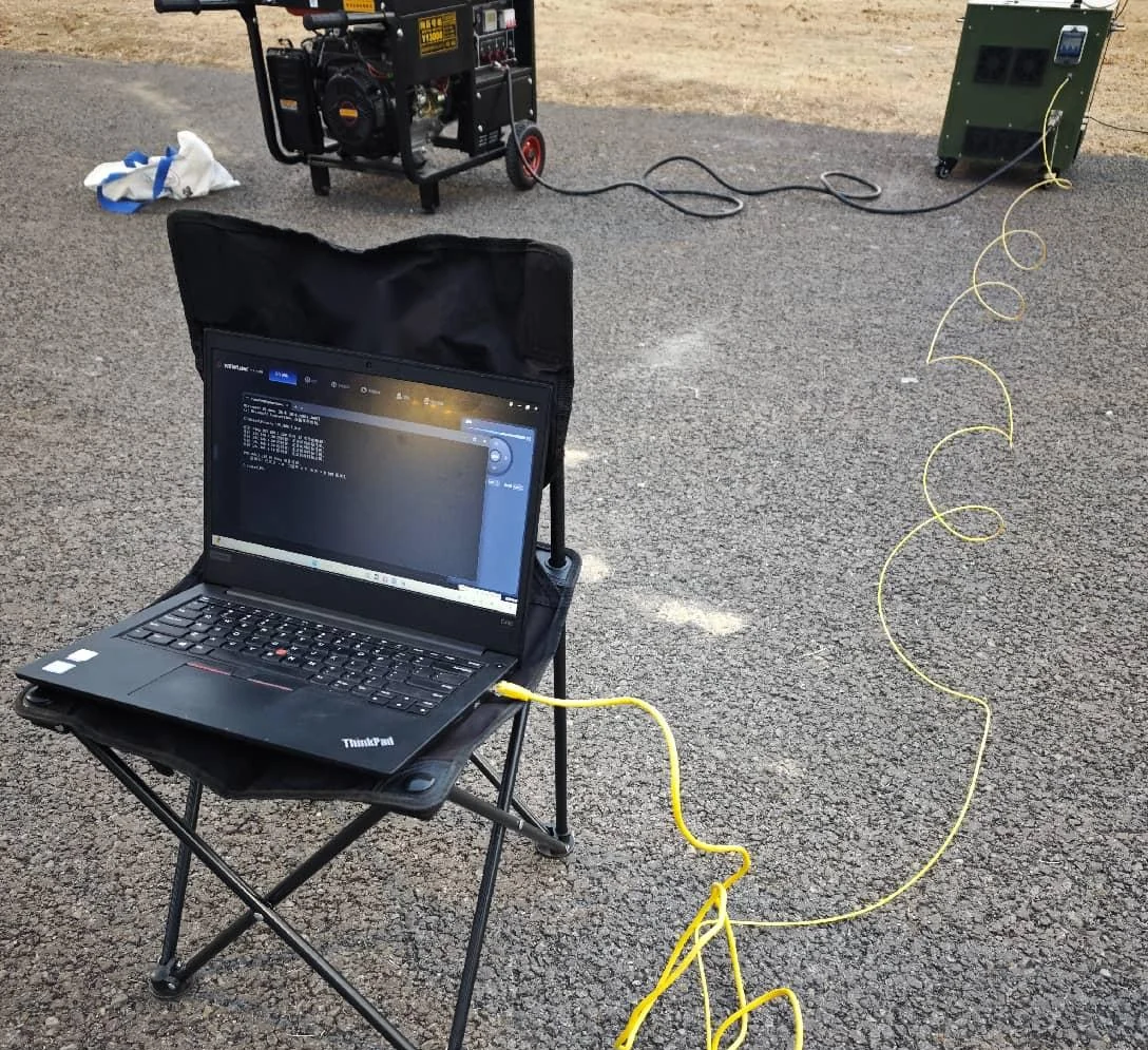
Field monitoring laptop, generator, ground station and optical-fiber cable during reference testing.
Operational Outcome Recorded in the Reference Project
Stable long-duration hovering without repeated battery replacement
Simultaneous visible and thermal imagery for day/night observation
Reliable HDMI video output for external command-center viewing
Primary control/video transmission through optical fiber rather than the normal RF link
Reduced operational interruption from battery changes and wireless-link management
Where This Architecture Is Useful
Persistent perimeter and site-security monitoring
Critical-infrastructure observation
Temporary event or incident command posts
Border, industrial or remote-area monitoring where a fixed elevated viewpoint is required
Locations where primary control/video should be carried by fiber because the RF environment is congested, sensitive or operationally undesirable
What Must Be Recalculated for a New Project
Scroll horizontally to read the full table
Frequently Asked Questions
Does the system use fiber for both control and video?
The reference project used optical fiber for the primary remote-control/data path and real-time HD video, with HDMI output to an external display.
Does fiber-optic control mean there is zero RF interference anywhere on the aircraft?
No. It means the primary control/video path can avoid dependence on the normal RF data link. Other aircraft functions may still use GNSS, backup radios or other RF systems.
How long is the reference tether?
150 m, with optical fiber integrated into the tether.
What payload did the project require?
The delivered UAV configuration used a 10 kg recommended payload class and carried EO + thermal imaging.
Can the ground station run from a generator?
The reference deployment was designed for field use and generator compatibility, provided the generator meets the ground unit input and power-quality requirements.
What information is required for a new surveillance proposal?
Target height, aircraft/payload mass, camera model and electrical load, required control/video interfaces, fiber protocol, HDMI/output needs, environmental conditions and available AC/generator source.
Talk to us about your configuration
For a persistent-surveillance project, send the target hover height, UAV/payload weight, EO/IR camera interfaces, control/video protocol, required fiber path and available ground source. We can size the power and data architecture together.
| Contact | Stella |
|---|---|
| Website | www.tethpower.com |
| stella@ | |
| WhatsApp / Tel | +86 177 1431 2943 |