The decision
Review voltage and cable requirements as a system. Higher transmission voltage can reduce current for the same transmitted power, but the station, cable and airborne converter must be designed and reviewed together.
Separate transmission voltage from aircraft voltage
A tethered power architecture can transmit power along the tether at one voltage and convert it on the aircraft to another. Keep those values in different fields. The voltage accepted by an airborne converter is not the same specification as its output to the aircraft.
The basic relationship between DC power, voltage and current helps explain why transmission voltage is part of cable selection. For a given transmitted power, a higher voltage means a lower current. Resistive loss also depends on current and conductor resistance. These relationships explain the tradeoff; they do not select a safe cable or converter by themselves.
Gather the cable information
Ask for the cable length, conductor specification, relevant electrical limits, connector details and mass information for the proposed configuration. Include the intended deployed length and how the cable will be handled by the reel. A cable comparison based on length alone misses information the aircraft and ground system need.
We need to review the voltage reaching the airborne equipment under the intended load. That review needs the actual cable and connectors, rather than a nominal wire size selected in isolation. Do not infer interchangeability between cables used with different station families.
Include the converter input window
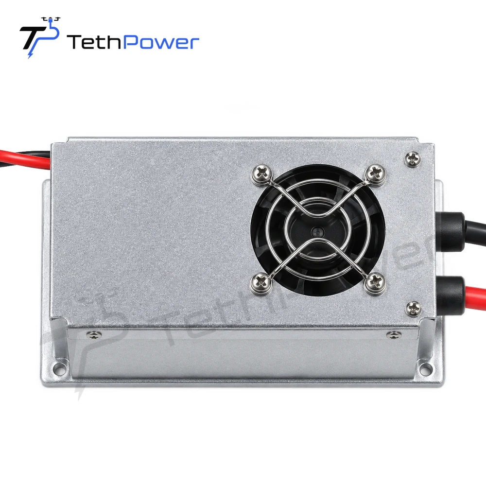
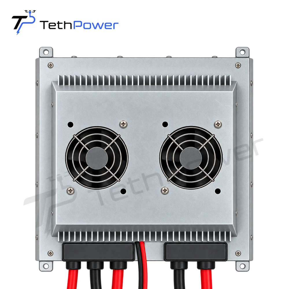
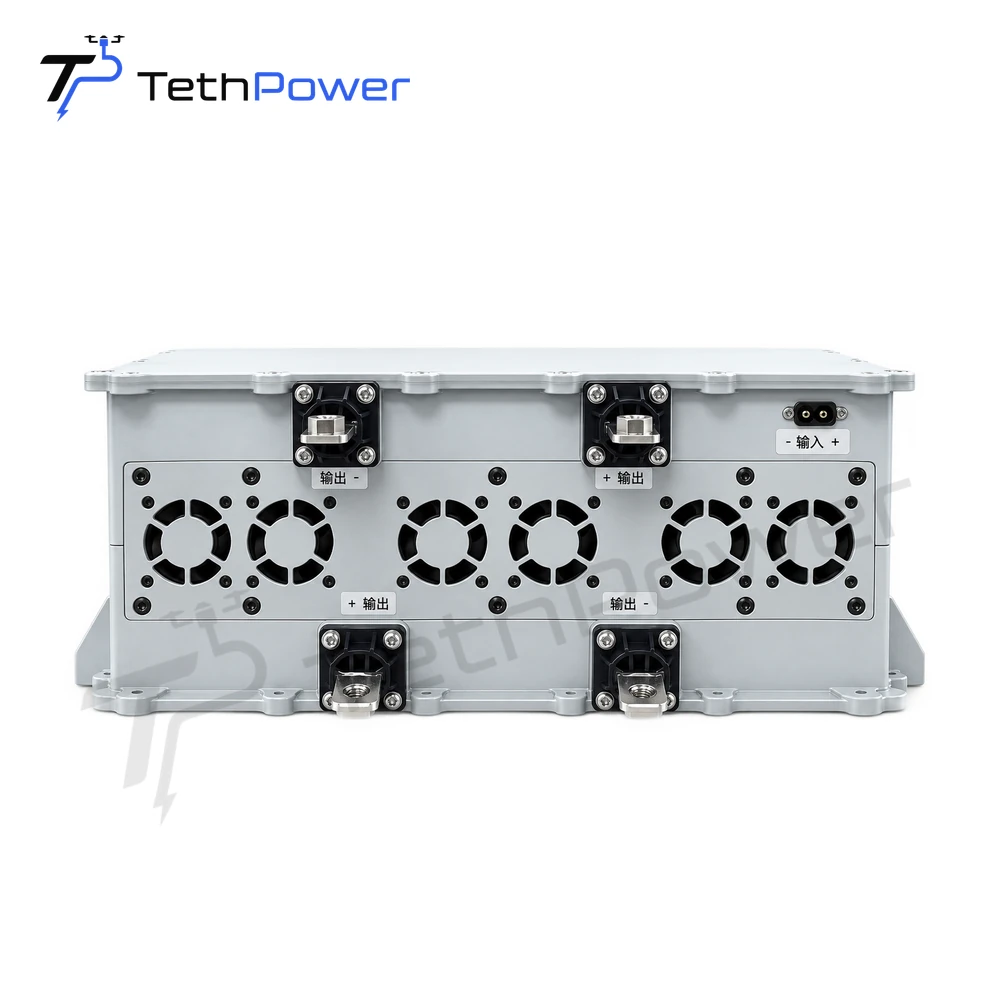
The converter must operate within its specified input range. Keep maximum-limit and normal operating values distinct. On TP-P1.5, for example, the specified 360–400 VDC operating range is separate from the 410–420 VDC maximum-limit condition.
At a purchasing level, the useful question is whether the proposed station, cable and converter meet the aircraft requirement across the intended operating conditions. Request a configuration-specific review rather than treating a voltage label as a compatibility guarantee.
Prepare a reviewable power-chain drawing
List the ground AC source, station model, station output, tether specification, airborne input and aircraft output in sequence. Add the sustained load, peak load and installation conditions. This simple drawing helps identify mismatched interfaces before purchasing.
For background on this architecture, see Vicor’s overview of tethered UAV power delivery. Its examples explain a general engineering approach; our model specifications remain those in the corresponding product specification and manual.