The decision
Choose the module against the aircraft's electrical and installation requirements, then check it within the complete ground-to-air power chain. A matching kW label is only one part of the decision.
Begin at the aircraft DC bus
Record the aircraft’s normal bus voltage and allowed voltage range, including the requirements of any separately powered payload. A battery’s nominal voltage is a useful starting point, but the integration review also needs the aircraft’s actual input limits. Identify whether the module supplies propulsion, a payload, or both; these are different load requirements.
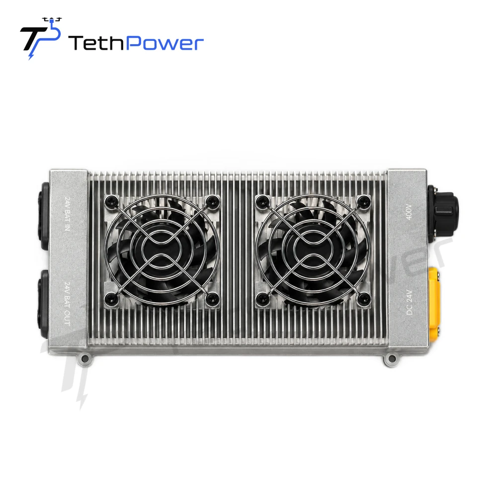
For example, the current TP-P1.5 specifications specify a 24 V nominal output with a 22.5–25.5 V range. They list a 360–400 VDC operating input. Those are different sides of the converter and should appear separately in a request for quotation.
Describe the load over time
Provide measured sustained demand and short peaks with their duration, aircraft weight and payload configuration. If measurements are unavailable, state that clearly and send the aircraft specification for an initial review. A maximum figure without its duration cannot describe the whole mission.
TP-P1.5 has 1.4 kW rated output and 1.5 kW peak output. The distinction matters when comparing it with a load that must run continuously. Read the conditions in each model’s specification instead of applying one model’s limits to the entire range.
Check the installation envelope
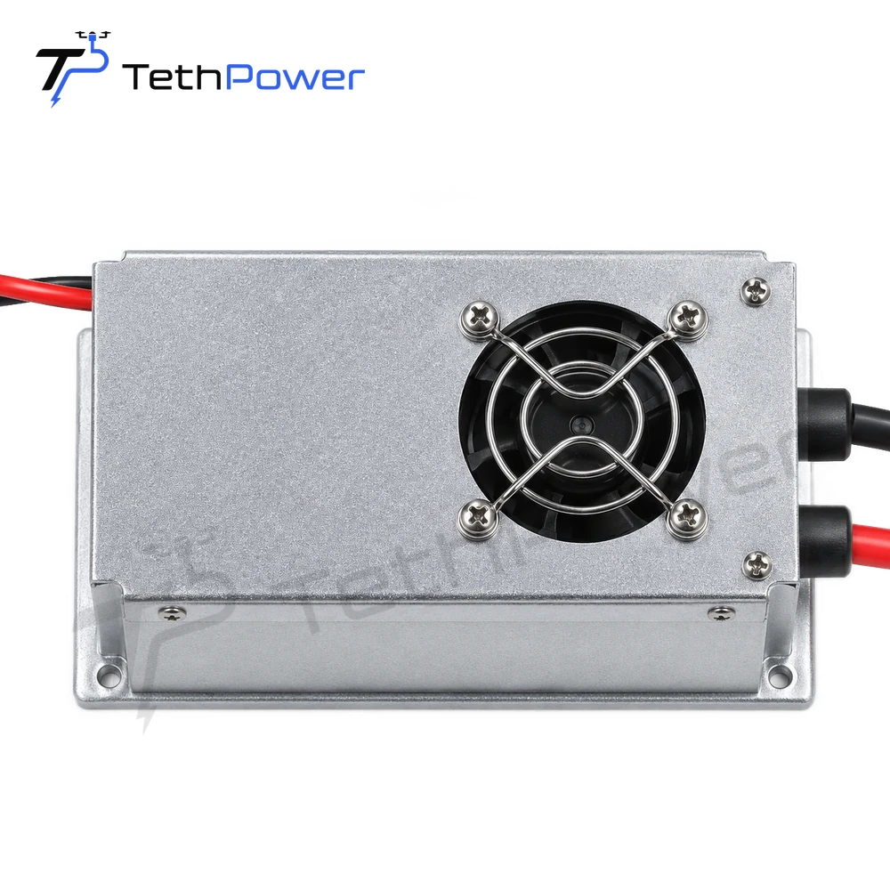
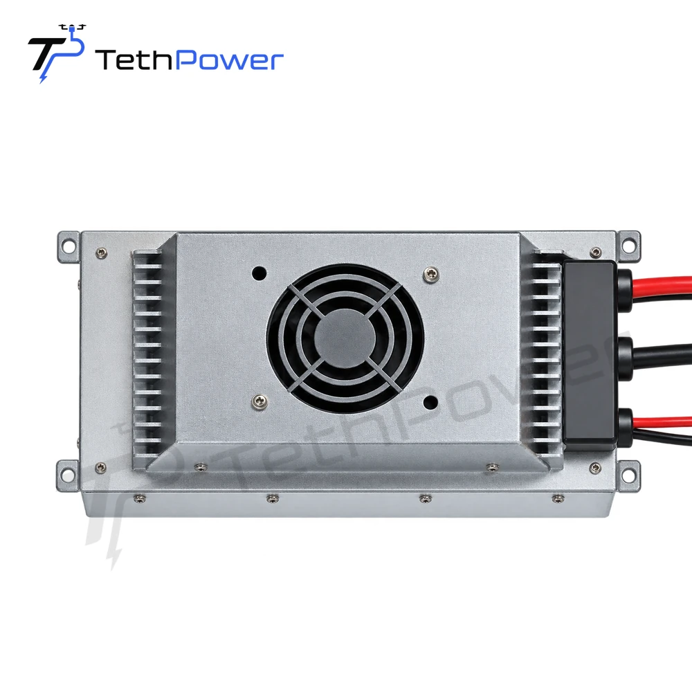
The module, mounting hardware and wiring all occupy space and add airborne mass. Share mounting drawings or photographs, available dimensions, airflow arrangements and connector requirements. Include the planned environment and operating altitude because the installation must be evaluated under the conditions in which it will be used.
Describe how the aircraft battery remains connected and what the aircraft should do following loss of ground power. The review should cover the module, battery interface and aircraft behavior together. A module feature alone does not describe the complete aircraft response.
Send one integration brief
Include the aircraft model or custom platform drawing, DC voltage range, sustained and peak demand, payload, weight allowance, tether length, ground station and available AC supply. Attach the relevant manual revision. This gives us enough context to review a matched configuration and identify any remaining interface questions before the quotation is finalized.
Browse the onboard power supply range for model-specific specifications, then use the product manuals to examine the candidate in more detail.
Compare the module’s job before choosing a model
For an aircraft power supply, the output must suit the aircraft DC bus. For a separately powered payload, start with that device’s own input and load. Keep both requirements visible if one installation contains separate supplies.
| Model example | Documented output | What to compare |
|---|---|---|
| TP-P1.5 | 24 V nominal, 22.5–25.5 V range | Aircraft input limits, 1.4 kW rated load and 1.5 kW peak demand |
| TP-P12 50V | 50 V output | Aircraft voltage, current requirement and the model’s input range |
These examples illustrate different output requirements. Use the individual product specifications for weight, cooling, mounting and operating conditions, then review the ground station and airborne module together.
If you only need an airborne module, enquire directly from the selected product page. For a new ground-and-air configuration, use Build. We can also discuss custom output and installation requirements that are not listed in the product range.