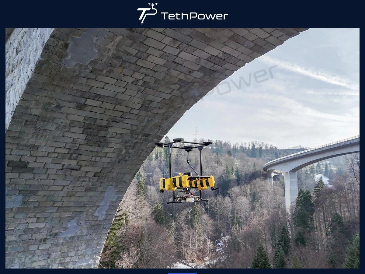
You can plan longer inspections of bridge soffits, girder undersides and near-water structures with continuous ground-supplied power. We bring together a deck-mounted ground power station and a matched airborne power module, while you provide the inspection aircraft and site-specific cable guides.
We present an integration concept, not a completed bridge-inspection delivery or a claim of whole-system flight testing. You need to validate the aircraft, power chain, cable route and recovery procedure for your bridge.
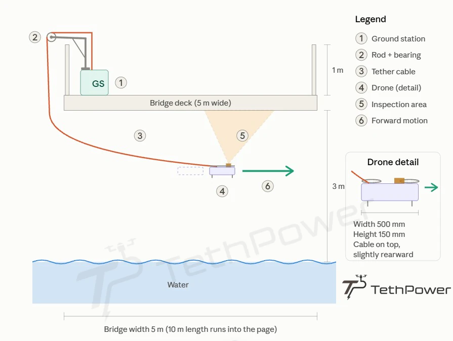
You can use this drawing to discuss the cable path. The 5 m deck width, 3 m inspection depth, 1 m parapet, 10 m length and 500 × 150 mm aircraft outline are illustrative dimensions, not clearance or aircraft requirements.
Why you need a different approach below a bridge
You have less room to manoeuvre around girders, parapets, diaphragms and other obstacles than during open-sky mapping. Repeated landings for battery changes can interrupt a long inspection pass. A poorly routed tether can rub against an edge, snag or sag toward the water. We review the power supply and cable route together so you can assess whether tethered operation suits your site.
How we arrange the power chain
We convert available AC power at the bridge deck to high-voltage DC, carry power through the tether and use a matched airborne DC-DC module to supply your aircraft at an approved voltage. You can retain the original flight battery in a validated backup power path. We need your aircraft voltage limits, measured continuous and peak power, sensor demand and complete cable path before confirming a match.
You can follow the arrangement as site AC input → ground power station → power tether → airborne module → your aircraft and sensors. Matching power-class labels alone does not establish compatibility.
What we supply and what you provide
Scroll horizontally to read the full table
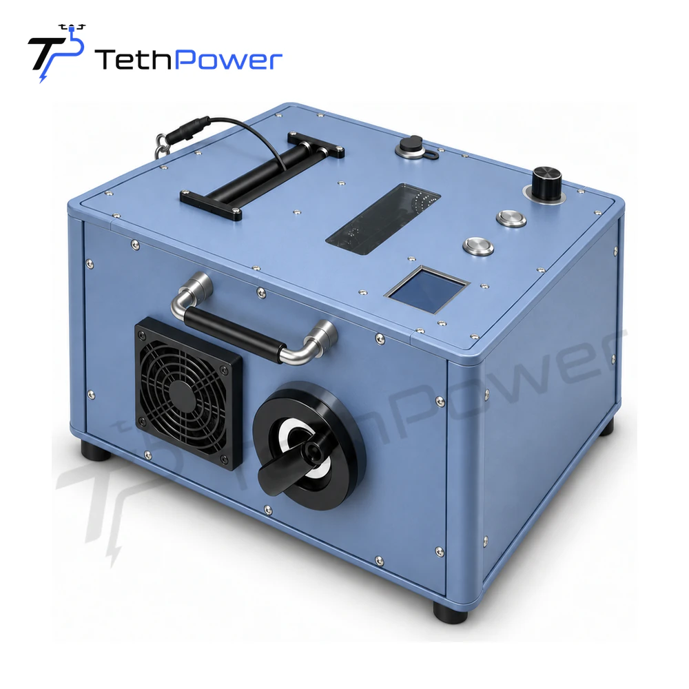
Our TP-T4 is the ground-side reference. You still need to confirm your airborne module, cable path and aircraft as a complete configuration.
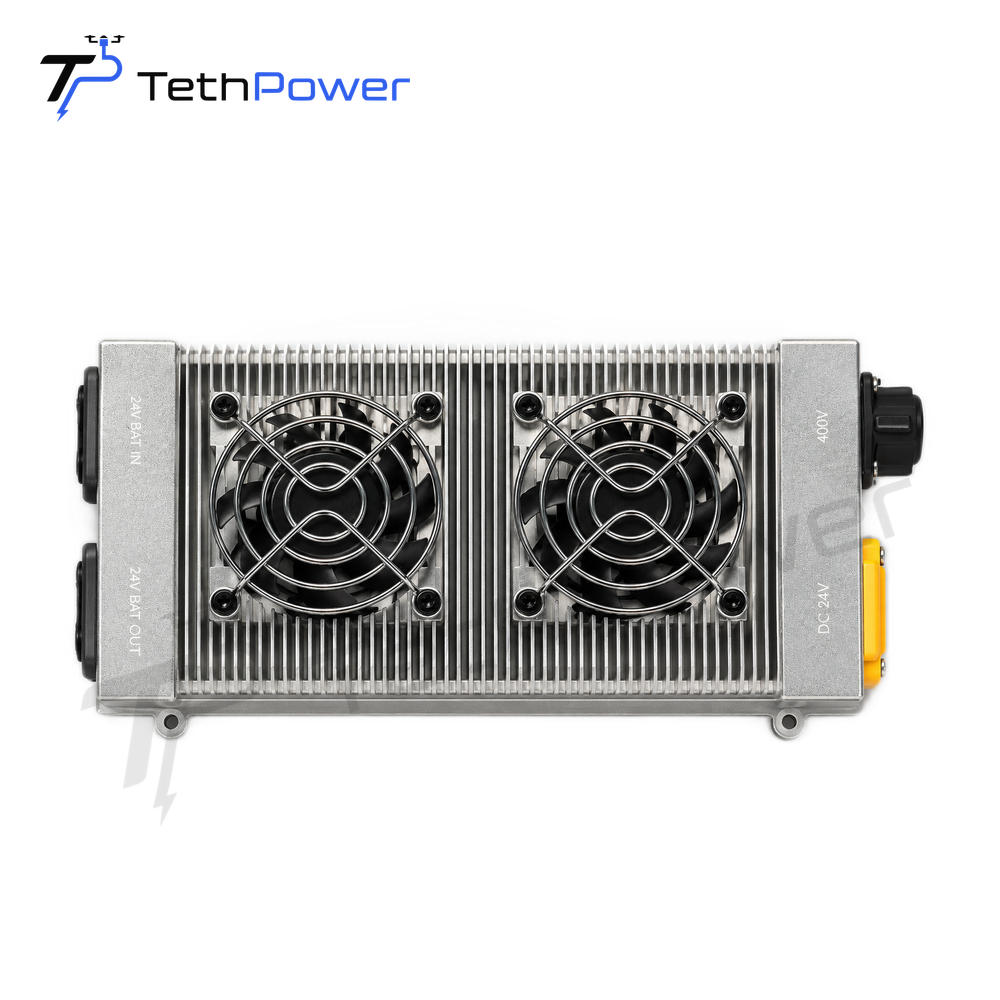
Our TP-P2.5 provides 2.2 kW rated output and 2.5 kW peak output. You need to allow for cable loss, aircraft demand and backup-battery wiring when checking compatibility.
Two cable guide points with different jobs
You use the upper guide or pulley to change the cable direction from the deck toward the inspection zone. You use a separate lower pole and smooth ring where the cable could rub against the bridge corner. You should not treat these two locations as the same guide.
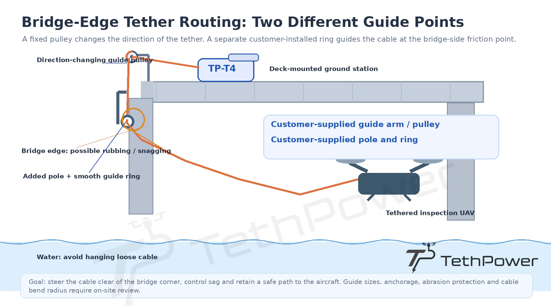
You design and supply both guide structures. You need to check anchoring, free rotation, contact surfaces and cable bend radius before use.
Check the full cable path during horizontal travel, descent and recovery. Keep sufficient clearance from the bridge, aircraft and water. Inspect wear and confirm an emergency recovery procedure before operating.
Keep the cable clear of your propellers
You can use a scorpion-tail guide to route the final cable section outside the propeller zone. You gain mechanical separation, but you still need to supervise slack, aircraft attitude and cable movement. You cannot eliminate every entanglement risk with a guide alone.
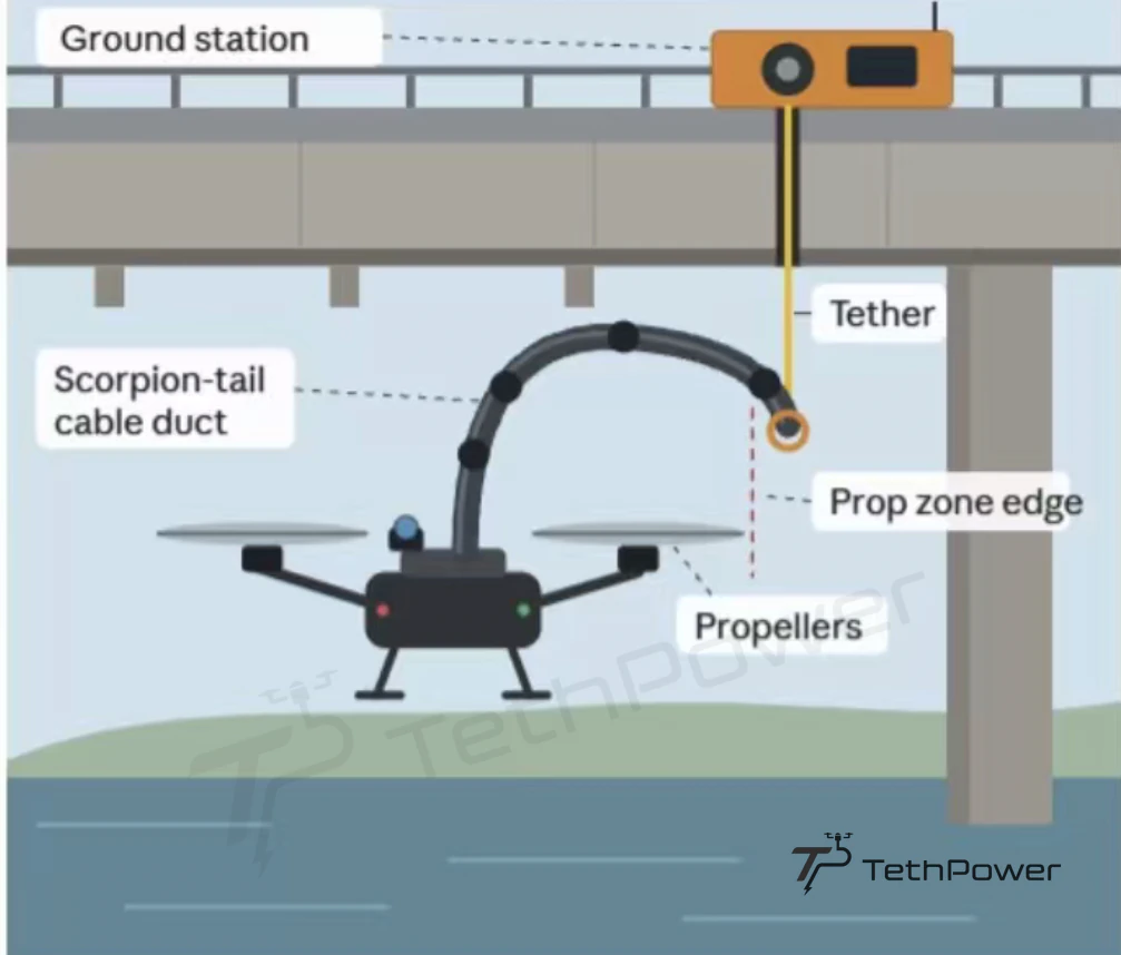
You need to validate the guide dimensions and installation on your aircraft. We show the routing principle, not a standard supplied accessory.
Control payout during your inspection
When you descend below the bridge, avoid continuous strong retrieval force that could pull the cable across your flight corridor. Use an appropriate payout mode or carefully managed release, with enough control to avoid excessive slack. Our TP-T4 supports passive payout and active rewind. The specified maximum rewind speed of ≤ 2 m/s is not a target for every flight phase.
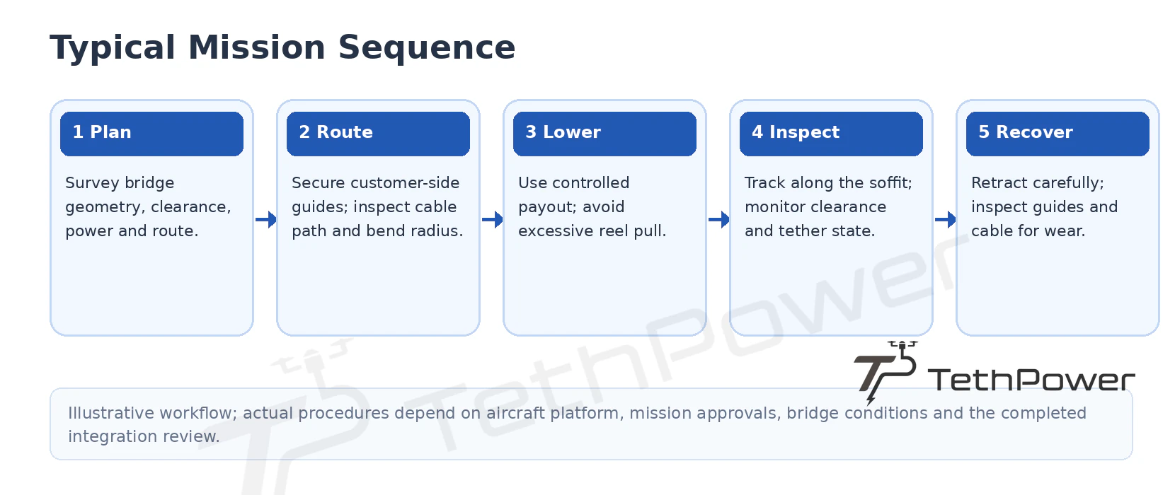
You can use this sequence for planning discussions. Follow your aircraft-specific procedure and site operating requirements during the actual mission.
Check whether your bridge is suitable
You can consider this arrangement for routine visual inspection of accessible soffits, girder undersides and near-water structures where you have bridge-deck access for the station and guides. Measure the actual clearance and cable path rather than copying the illustrative dimensions.
Review dense cross-bracing, sharp corners, obstructed routes, bridge-induced turbulence and high winds carefully. You also need adequate over-water recovery space and control of cable sag. Do not assume you can use precise geotagging or autonomous waypoint flight beneath a structure with poor GNSS reception.
Discuss your inspection configuration with us
Tell us about the bridge and the aircraft you plan to use. We can discuss the TP-T4 / TP-P2.5 reference with you, then review battery voltage, continuous and peak power, sensor load, clearance, inspection length, cable routing and AC input before confirming the power margins and supply scope.
- Review our TP-T4 ground power station.
- Review our TP-P2.5 airborne power module.
- Read our tethered drone FAQ.
- Discuss ground and airborne module selection with us.
- Contact us about your bridge inspection project.
Frequently Asked Questions
Can I inspect the underside of a bridge with a tethered drone?
You can consider tethered inspection when your aircraft fits the available clearance and you can establish a controlled cable path. We review your aircraft power demand, ground station, guide layout and recovery plan together before confirming a configuration.
How does tethered power help with bridge soffit inspection?
We supply power from the ground so you can reduce repeated battery-change interruptions during a planned inspection pass. Your actual inspection window still depends on your aircraft, available power, weather and operating procedure.
What rated power can I use from TP-P2.5?
Our TP-P2.5 provides 2.2 kW rated output and 2.5 kW peak output. You can select 24 V or 48 V configurations for suitable 6S or 12S systems. Module weight is 532 g. We check your complete power chain before confirming compatibility.
Do you supply the pulley, scorpion-tail guide and extra guide ring?
You design and supply these site-specific guide structures for this reference arrangement. We do not include these structures in our standard power-equipment supply. We confirm the exact equipment scope in your quotation.
Why should I add a guide pole and ring at the bridge edge?
You can use a suitable smooth guide ring to reduce direct cable rubbing at a bridge corner and control unwanted sag toward the water. You need to validate the guide anchoring, cable contact surfaces and bend radius for your site.
How should I manage the tether while descending?
Use controlled payout or another validated cable-management method. Avoid excessive retrieval force while keeping slack under control. Our TP-T4 supports passive payout and active rewind at ≤ 2 m/s; you should not use this maximum as a target for every flight phase.
Do you supply my inspection aircraft?
We focus on the ground power station, airborne power module, specified tether and power-chain integration. You provide the inspection aircraft, sensors and site-specific guides unless we agree a separate supply scope with you.
| Contact | Stella |
|---|---|
| Website | www.tethpower.com |
| stella@ | |
| WhatsApp / Tel | +86 177 1431 2943 |