Quick answer: A tethered eVTOL test setup moves the main energy source to the ground. High-voltage DC travels through a lighter tether, while an onboard converter regulates the voltage required by the aircraft bus. This can extend powered test windows from battery-limited minutes to multi-hour engineering sessions, subject to the aircraft and test-safety plan.
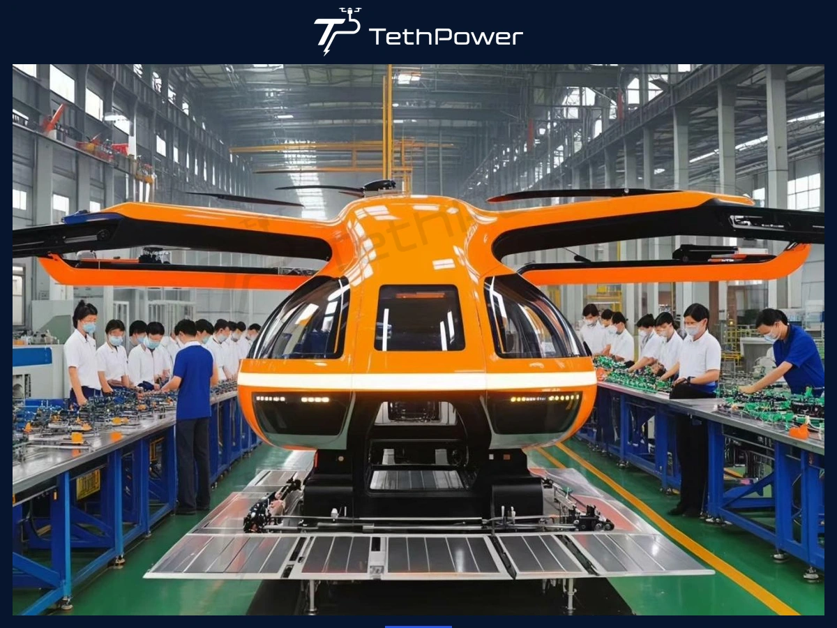
Lightweight eVTOL platform in a manufacturing / R&D environment.
Why eVTOL R&D Teams Use Tethered Power During Early Testing
Early eVTOL development often requires repeating the same hover, propulsion and control experiments many times. Battery-only test windows can make long-duration motor runs, thermal stabilization, vibration observation and redundancy testing harder to schedule because the test must stop when the battery reaches its operating limit.
A tethered power architecture changes that constraint. The ground unit provides the bulk energy, the tether transmits it at high voltage to reduce cable current, and the onboard converter supplies the aircraft at its required DC bus voltage. The aircraft can then be tested for longer periods without treating battery energy capacity as the primary duration limit.
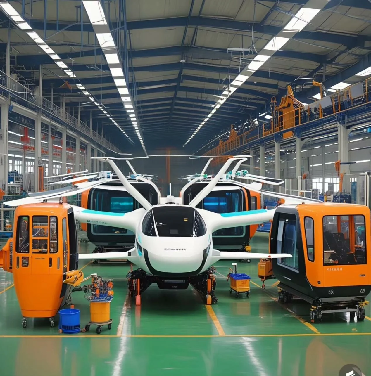
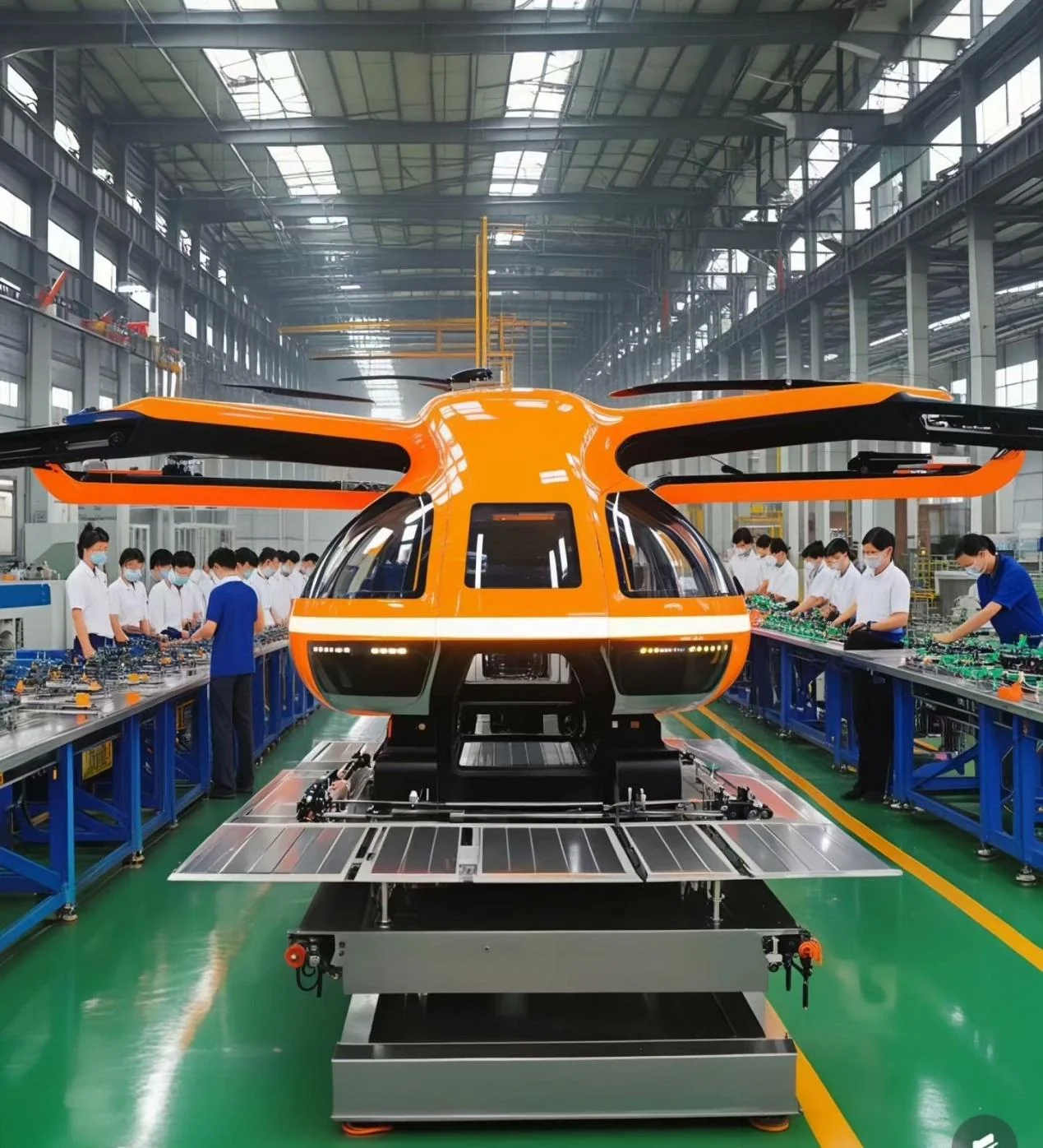
Multiple lightweight eVTOL platforms in an R&D / production setting.
Test Activities That Benefit from Longer Powered Windows
Motor endurance and sustained-output testing
Thrust stability and propulsion efficiency mapping
Flight-control tuning and repeatable hover experiments
Redundant propulsion switching tests
Vibration and acoustic observation over longer thermal cycles
Emergency-condition and fault-response simulation within a controlled test plan
Powertrain and DC-bus validation before broader free-flight campaigns
Reference Architecture
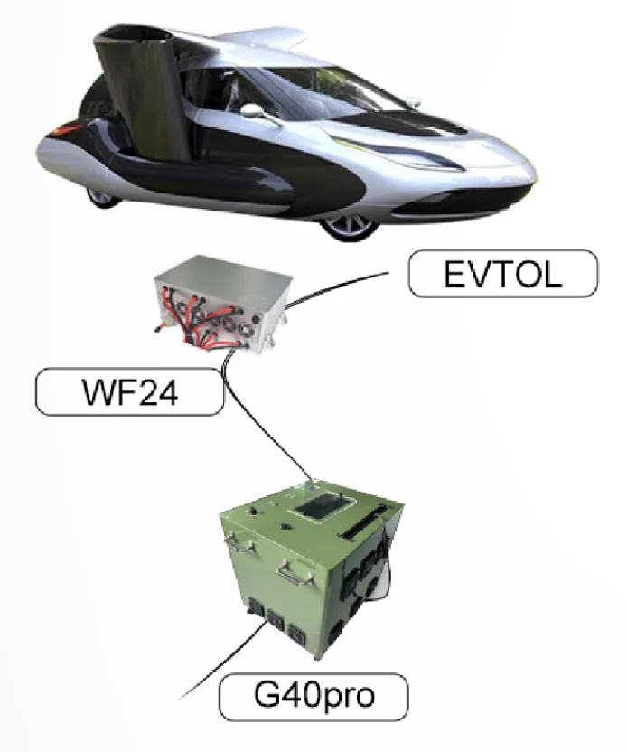
Reference architecture: ground high-voltage source, tether, WF24 airborne conversion and eVTOL DC bus.
Scroll horizontally to read the full table
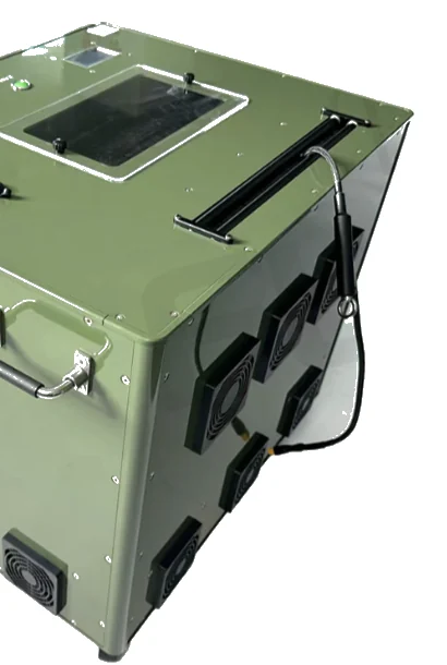
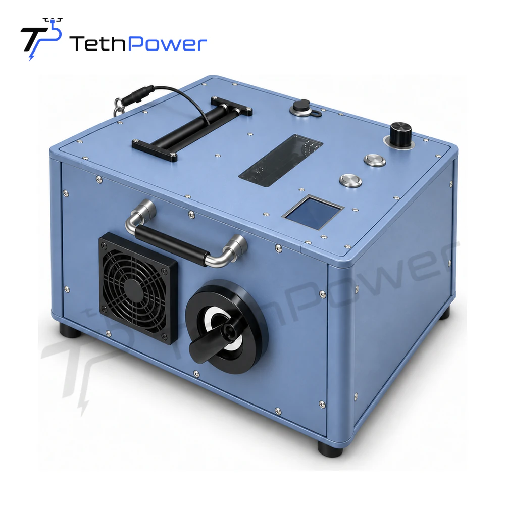
Reference G40Pro-class ground high-voltage power unit.
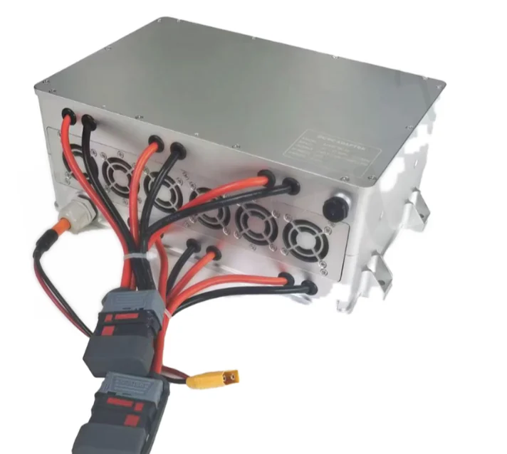
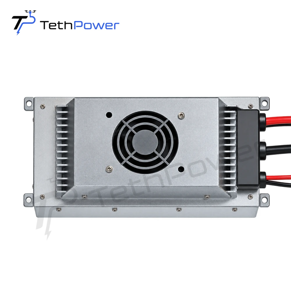
Reference WF24-class onboard DC/DC power module.
Reference Overseas eVTOL Project Logic
This overseas lightweight eVTOL test project uses a 1,000 V DC tethered transmission stage and an onboard regulated 14S / approximately 60 V aircraft bus. The purpose was not to make the aircraft permanently tethered; it was to create a repeatable engineering power source for hover, propulsion and control tests before later free-flight development.
Safety and Test-Envelope Considerations
Power tether vs. mechanical restraint - a power cable should not automatically be treated as a certified arresting tether. If physical flight-envelope restraint is required, it should be engineered separately for the expected loads and failure cases.
Emergency battery / backup logic - define what happens if ground power, tether voltage or onboard conversion is interrupted.
Cable force and aircraft dynamics - tether weight, drag and payout force can affect hover behavior and flight-control tuning.
Thermal management - long test runs expose motors, ESCs, converters and connectors to thermal conditions that short battery flights may not reveal.
Ground electrical safety - high-voltage DC architecture requires appropriate interlocks, grounding, insulation, emergency stop and operating procedures.
Authorization - a constrained tethered test may simplify some site risk controls, but regulatory approval is jurisdiction- and test-specific and should never be assumed.
What we need to size an eVTOL test system
Scroll horizontally to read the full table
Frequently Asked Questions
What is the main benefit of tethered power in eVTOL testing?
It decouples many hover and propulsion tests from onboard battery energy capacity, allowing longer and more repeatable powered test windows.
Does the tethered setup replace batteries completely?
Not necessarily. A development team may retain a battery for transient support, emergency backup or later free-flight phases. The exact architecture depends on the aircraft power bus and safety strategy.
Can the system be used for propulsion tests without free flight?
Yes. Ground/high-voltage and onboard conversion can support controlled hover or other test-rig configurations where continuous aircraft-bus power is useful.
Does tethering automatically make urban or restricted-area testing legal?
No. Tethering can constrain the operating area, but site permission and aviation requirements remain jurisdiction-specific.
What should be provided for initial selection?
Bus voltage, continuous/peak power, MTOW, spare payload, target height, ambient conditions, ground source and backup strategy.
Talk to us about your configuration
Send the eVTOL bus voltage, continuous and peak propulsion power, MTOW/payload margin, target hover height and available ground supply. We can build the power-chain proposal from those engineering inputs.
| Contact | Stella |
|---|---|
| Website | www.tethpower.com |
| stella@ | |
| WhatsApp / Tel | +86 177 1431 2943 |