
At a glance
Compare actual voltage ranges and the stated power ratings with the aircraft load and ground supply.
Start with both sides of the converter
If your aircraft uses a 24 V bus, start with the voltage range it can accept. Two modules with the same nominal voltage can have different output ranges. Compare the ground station’s voltage at the module input with its operating range, and the aircraft’s permitted DC bus range with the module’s actual output range.
| Model | Input | Output | Power and current |
|---|---|---|---|
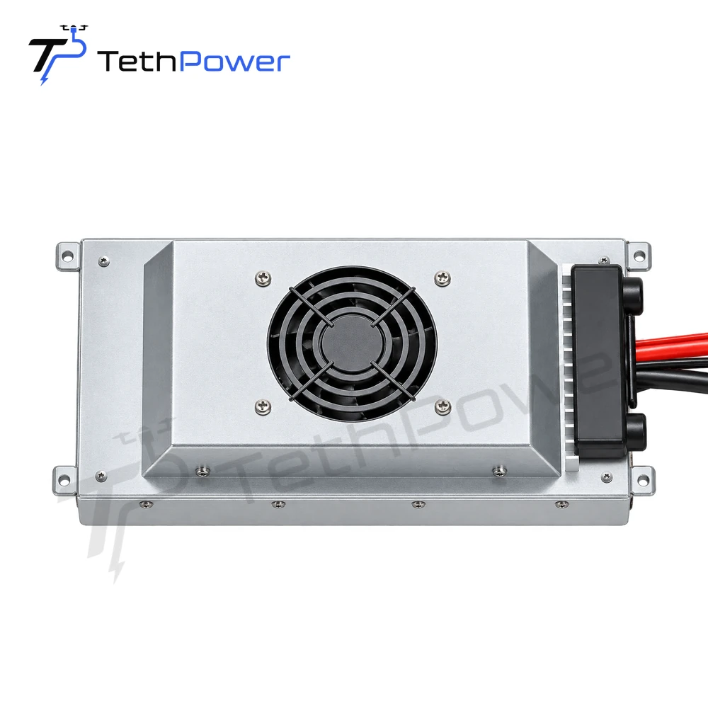
| TP-P3.5-80024 | 680–800 VDC | 24 V nominal; 21–25.2 VDC | 3.5 kW maximum; 120 A rated |
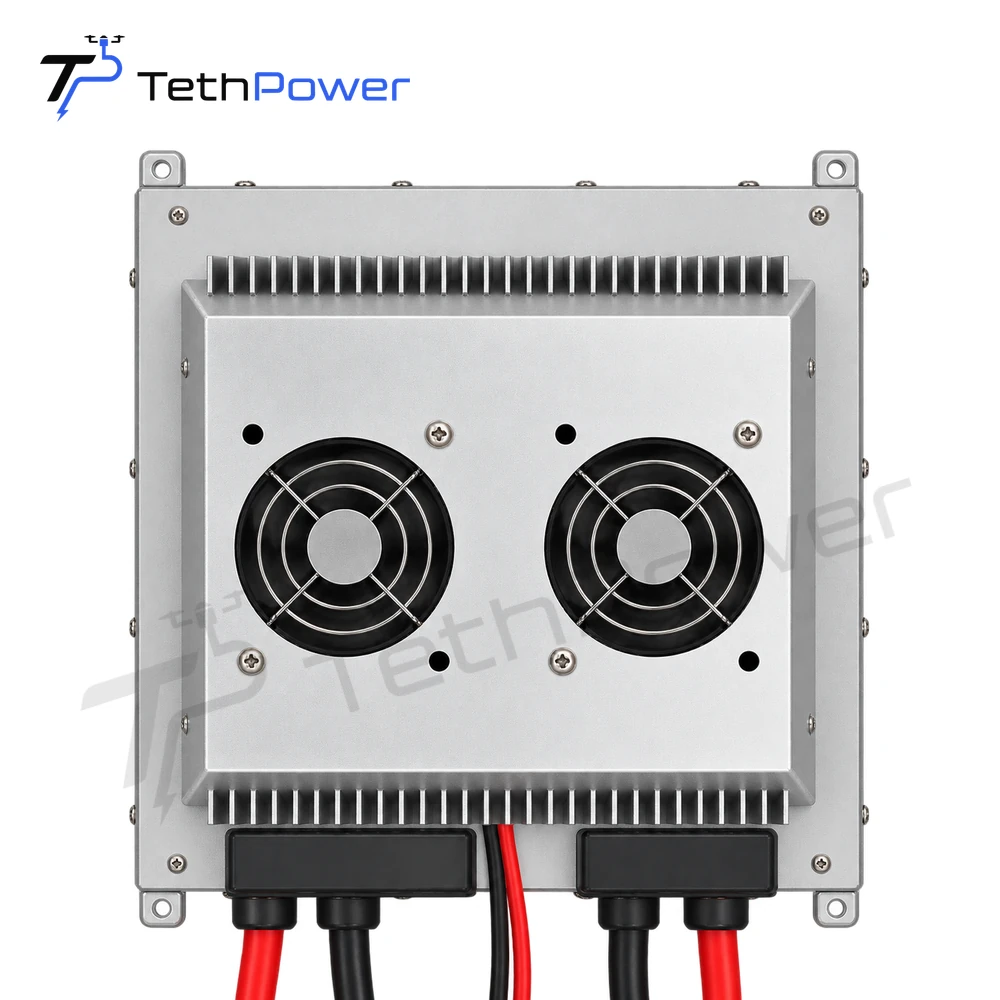
| TP-P5 | 680–800 VDC | 24 V nominal; 23.5–24.5 VDC | 5 kW rated; 210 A rated |
The 3.5 kW figure is a maximum, while 5 kW is rated output. Do not treat them as equivalent continuous ratings. Compare sustained load and peaks, including their duration, with the relevant specifications.
Discuss the whole installation
Voltage drop along the tether, connectors, cooling, mounting and the battery interface also need review. Tell Stella about your existing ground station and tether, the aircraft’s operating voltage range, sustained and peak loads, and any available interface documents. Contact us to discuss which module merits further evaluation for your installation.