
At a glance
Start with the aircraft's permitted bus voltage and actual sustained and peak loads. Then compare input range, module weight, cooling and the ground-to-air connection as a complete installation.
Start with the aircraft, not the largest number
If your aircraft uses a 50 V-class power bus, the right airborne module depends on more than its nominal output. The aircraft must accept the module’s actual voltage range, carry its weight and have space for mounting and cooling. Its propulsion and mission equipment also need enough power at the conditions you expect to use.
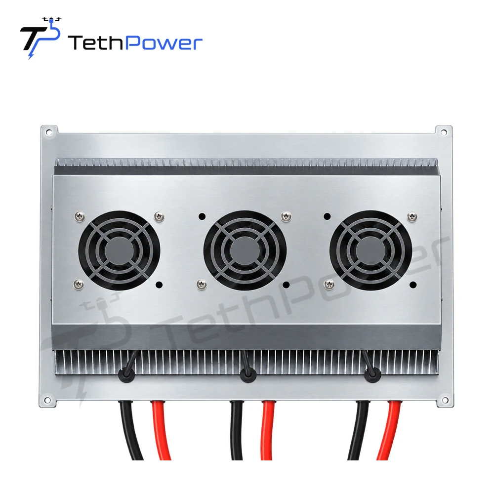
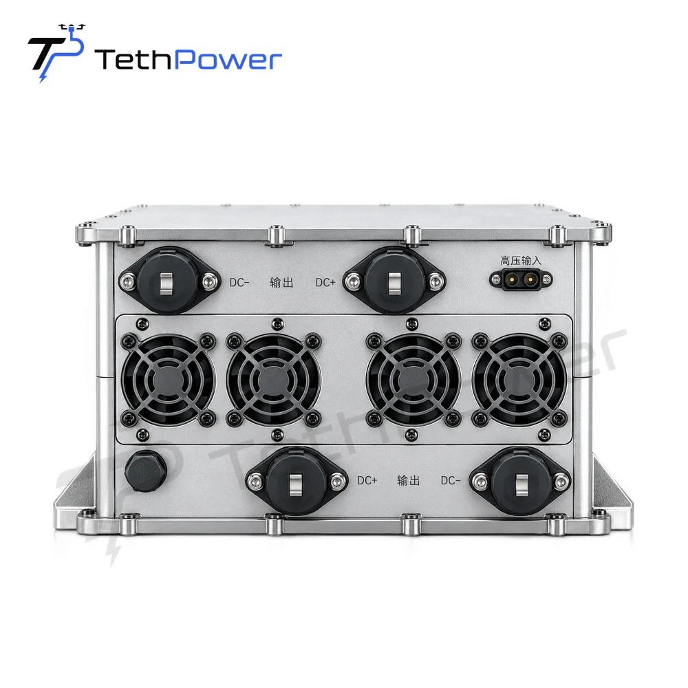
The table compares three of our airborne modules. The TP-P12 shown here is the 50 V version; it is a separate product from our other TP-P12 voltage version. All three require a suitable ground station and tether. The table is a starting point for a project review, not a list of pre-approved aircraft or ground-station pairings.
| Airborne module | Documented tether input | Nominal output and range | Rated output | Module weight | Enclosure rating |
|---|---|---|---|---|---|
| TP-P12, 50 V | 900–1000 VDC | 50 VDC; 49.5–50.5 VDC | 12 kW; 240 A | 3 kg | IP65 |
| TP-P16 | 850–1000 VDC | 50 VDC; 49.7–50.3 VDC | 16 kW; 320 A | Approx. 6.5 kg | IP54 |
| TP-P18 | 900–1000 VDC | 50 VDC; 49.5–50.5 VDC | 18 kW; 360 A | 8.2 kg | IP65 |
Use sustained demand and weight together
Compare the aircraft’s sustained power requirement with the module’s rated output. Include the propulsion system and every payload supplied from the same bus. Separately record short-duration peak demand and how long it lasts. A rated output is not a promise that the module can supply an unspecified peak; a separate peak-power rating is not stated for these three modules. See rated, continuous and peak power.
For example, when a project is being assessed around TP-P12, moving to TP-P16 raises the rated figure from 12 kW to 16 kW, but the listed module weight also changes from 3 kg to approximately 6.5 kg. The aircraft’s available payload margin must include that difference together with its mission equipment and the tether it carries. A heavier module is not automatically a better fit just because its rated power is higher.
Check the tether input and the aircraft output separately
The 50 V figures describe the module output to the aircraft. The 850–1000 VDC or 900–1000 VDC figures describe its input from the tether. They are different sides of the converter. Confirm the voltage available at the module under the intended load and cable conditions, not just a ground-station label. The module’s output range must also fit the aircraft’s permitted bus range.
A matching number alone does not establish an electrical or mechanical connection. Review the connectors, protection coordination and any battery interface as part of the complete setup. Our guide to matching a ground station and airborne module explains what to compare at each interface.
Plan the physical installation
All three modules have integrated forced-air cooling. Allow for the airflow and installation conditions required by the selected model. Check mounting, cable routing, operating environment and the space available on your aircraft. The IP54 and IP65 figures in the table describe the stated enclosure ratings; they do not replace a review of the complete installation or establish warranty coverage for water exposure.
If you already own a ground station, tether or aircraft, you can start with that equipment rather than replacing everything. Send Stella the aircraft’s allowable supply range, expected sustained and peak loads, payload allowance, existing equipment models and a sketch or photos of the intended mounting. We can review which of these modules merits closer consideration and what else must be checked before a quotation. Discuss your project with Stella.